Coils and ferrites – selection made easy
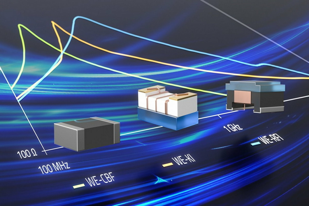
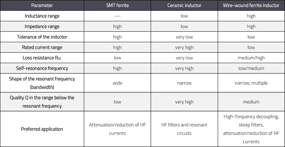
Inductive components are available in numerous forms. SMT versions are very popular, as they are easy to mount on circuit boards. However, not all inductors are the same. We’ll demonstrate this using three representatives of SMT inductors: ceramic, SMT ferrite and wire-wound ferrite (Figures 1 and 2).
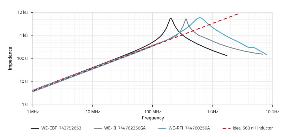
The components were selected so that they have a similar impedance curve in the range below their impedance peaks. The differences in the impedances can be seen in the area of the peaks. The SMT ferrite has its maximum at the lowest frequency and the wire-wound ferrite at the highest. The ceramic inductor has the steepest rise and fall in the area of the impedance maximum and therefore the highest quality (Q).
The impedance (Z) is a vector combination of resistance and phase. The ohmic resistance (R) has a dissipative property; energy is converted and not recovered. The reactance (XL) is the part of the impedance that’s generated by the inductance. The phase is the delay between a voltage applied to the component and the current flowing through the component. Both the ohmic resistance and the reactance vary with the frequency, and therefore also in the phase.
Electrical parameters in comparison
For inductors without a ferrite core (WE-KI), the inductance (L) is given as a value in the data sheets. Although the inductance value is specified at a particular measuring frequency, the value below the resonant frequency is almost constant. On closer inspection, the reactance of the inductance does not increase linearly with the frequency. Two effects increase the impedance of the air-core coil: the increase in reactance due to Lenz's law and the increase in resistance due to the skin effect.
In the purely inductive circuit, the air coil is connected directly to the AC supply voltage. As the voltage rises and falls with the frequency, the self-induced counter-electromagnetic force (EMF) in the coil also rises and falls as a function of this change. This self-induced back EMF is directly proportional to the rate of change of the current through the coil (Lenz’s law) and therefore increases with frequency. Consequently, the reactance of the inductance also increases with the frequency; this curve is proportional.
A further increase in impedance is caused by the skin effect. At low frequencies, a conductor uses its entire cross-sectional area as a transport medium for charge carriers. If the frequency is increased, an increased magnetic field in the direction of the center of the conductor represents an impedance for the charge carriers, whereby the current density in the center of the conductor decreases and the current density at the edge of the conductor increases. This increased current density near the edge of the conductor is known as the skin effect. The effect increases with frequency and also occurs with all other inductors with a ferrite core.
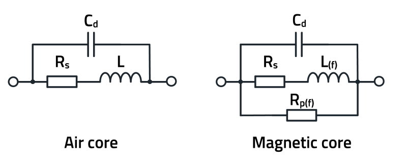
The resonant frequency of the inductance without a ferrite core is primarily caused by the parasitic capacitance between the individual windings. Whenever two conductors are arranged in close proximity but separated by a dielectric and there is a voltage difference between them, a capacitor is formed. The chain of these winding capacitances is connected in parallel to the winding inductance and thus forms a parallel resonant circuit. In addition, there is a parasitic capacitance between the connections (solder pads), which is parallel to the winding capacitance. This results in a parasitic total capacitance in parallel with the winding as an equivalent circuit (Figure 3).
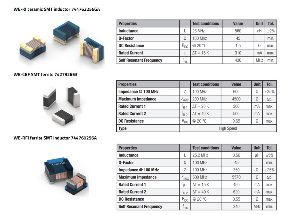
For inductors with a ferrite core (WE-RFI) and SMT ferrites (WE-CBF), the data sheet doesn’t specify an inductance value, but an impedance at a measuring frequency. It can also be seen that the SMT ferrite has the highest tolerance, and the inductance without ferrite has the lowest tolerance. As the WE-KI inductor doesn’t have a ferrite core, it requires more turns of wire for the same impedance than the components with ferrite, which is why the WE-KI also has the highest wire resistance.
A quality factor is specified for both the WE-KI and the WE-RFI, but not for the WE-CBF. This Q factor is a measure of the dissipative property of an inductor. Inductors with a high Q factor have low losses and a narrower impedance curve. Inductors with a low Q factor, on the other hand, have higher losses and a broader impedance curve. The size of the maximum impedance of the inductor is related to the quality factor. Low-loss inductors with a high Q factor have a very high maximum impedance, while an inductor with high losses has a lower maximum impedance. By changing the way an inductor is wound or the core materials used, the impedance maximum and the frequency range of the impedance maximum can be aligned.
Magnetic core materials
In many radio frequency applications where large inductance values are required in a small space, inductors with an “air core” can’t be used due to their size. The design of the inductor becomes smaller if the air core is replaced by a core material with a higher magnetic permeability. A high permeability leads to a high inductance, but it’s usually also associated with higher core losses. If the size remains the same, the inductance value is maintained despite the reduced number of windings. This allows several advantages to be realized: a smaller size due to the smaller number of turns required for a given inductance, an increased Q as fewer turns means less wire resistance and the possibility of modifying the impedance of the inductance over frequency through targeted selection/mixing of the core material.
The use of magnetic cores does present some problems. Any core material is highly lossy above a specific frequency range. For example, adding a magnetic core to an air core coil can reduce the quality of the inductance depending on the material used and the operating frequency. Also, the permeability of all magnetic cores changes with frequency and generally falls to a very small value at the upper end of their operating range. It eventually approaches the permeability of air and becomes ‘invisible’ to the circuit. The higher the permeability of the core, the more sensitive it is to temperature fluctuations. The inductance of the coil can therefore fluctuate considerably over wide temperature ranges. Furthermore, the permeability of the magnetic core changes with the applied signal level. If the current through the inductance is too high and the magnetic flux density through the core is therefore too high, the core will saturate.
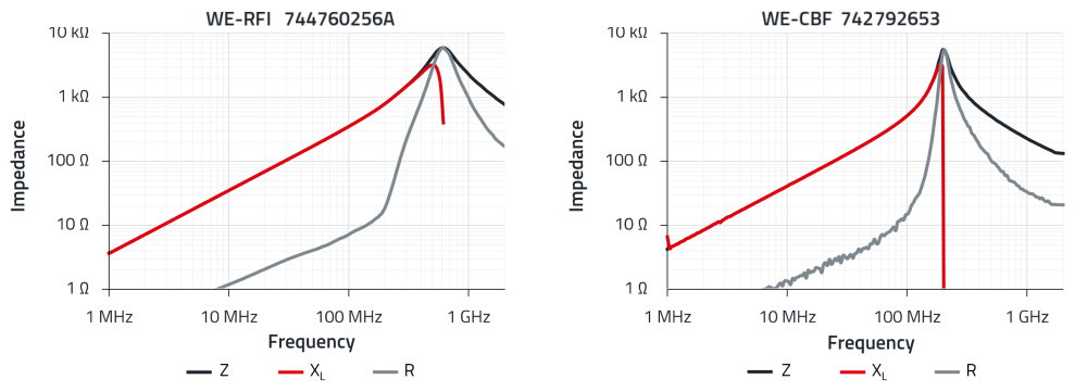
These problems can be overcome if care is taken during the development stage to ensure that the inductors are selected correctly according to their use. For this purpose, the diagrams with the impedance, ohmic resistance and reactance curves are required (Figure 4). The course of these curves over the frequency depends strongly on the magnetic properties of the core material.
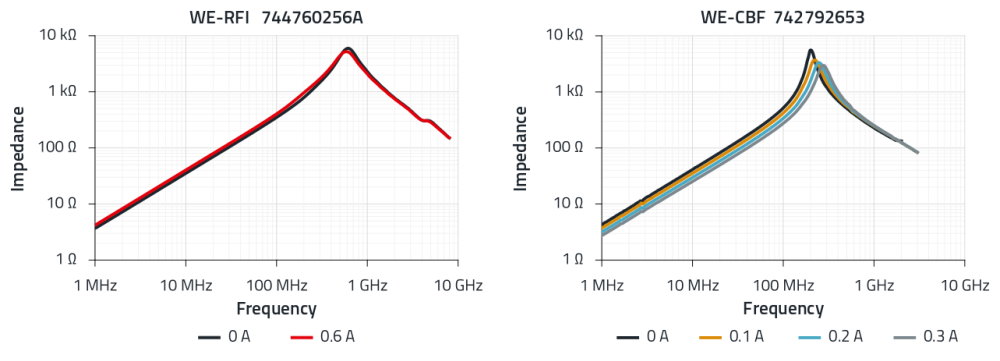
But that’s not all. Above the frequency, the saturation effects exhibited by magnetic materials depend primarily on the magnetic flux density, ie the current flowing through the ferrite inductor. This is referred to as core saturation, an effect that ‘air inductance’ doesn’t have (Figure 5). Wire-wound inductors are less sensitive to DC bias than SMT ferrites for the same rated current. The influence of bias magnetizations of different strengths on the impedance curves can be simulated for all part numbers using a platform like Würth Elektronik Redexpert.
More information can be found in Würth Elektronik’s application note on the topic. It suggests a more detailed setup for measuring impedance behavior and presents a simple method for measuring impedance. In addition, the various fields of application of the different inductance types are illustrated using the example of a 20 MHz signal generator.


