Why a stable inductance value doesn’t always guarantee stable performance at high temperature and high frequency.
Modern power converters are expected to deliver more power in less space. Silicon carbide and gallium nitride switches help designers increase switching frequency and power density, but they also place more stress on passive components. The power inductor must handle high DC current, ripple current and elevated temperature without compromising efficiency or reliability.
Molded power inductors are widely used for this purpose. Their core is made by compacting magnetic metal powder around the winding. This construction offers effective magnetic shielding, low acoustic noise and a gradual saturation characteristic. It also supports high DC bias, which is valuable in compact DC/DC converters.
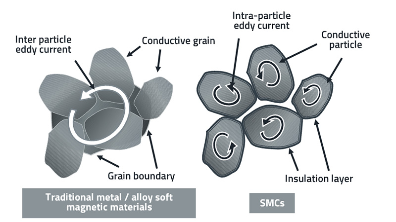
The magnetic particles are electrically conductive, so each particle receives a thin insulating coating. A binder holds the particles together. This creates many small electrical barriers throughout the core, limiting eddy currents while the particles still provide a magnetic path. The structure is often described as a soft magnetic composite.
Percolation
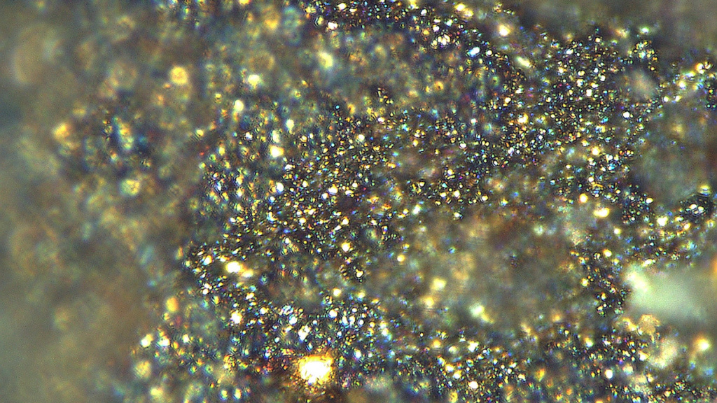
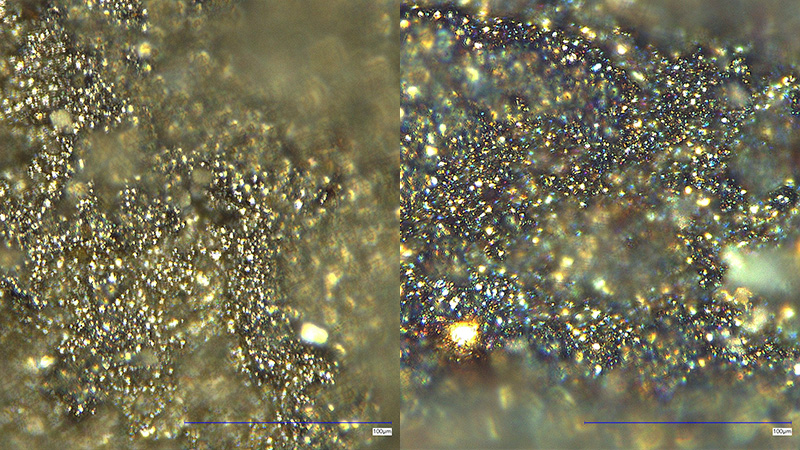
Under sustained high temperatures, the insulation coating and binder can degrade. High voltage can add further stress, for example through localized electric fields. Over time, the electrical insulation between particles decreases. As a result, small conductive paths begin to form inside the core, reducing the overall equivalent electrical resistance. This progressive loss of insulation, leading to the formation of conductive particle agglomerates, is known as percolation.
Percolation doesn’t mean that the complete core suddenly becomes conductive. It’s a gradual change, which is exactly why it can be overlooked. The inductor may still show an acceptable inductance value at a standard test frequency, while its losses at the real switching frequency are already rising.
The new conductive paths allow more eddy currents to flow. These currents consume energy and convert it into heat. The inductor then heats up more at the same electrical load. Extra heat can accelerate further degradation, creating an unwanted feedback loop: Higher loss causes higher temperature, which in turn causes more loss.
The system-level effects can include reduced converter efficiency, unexpected component heating and reduced thermal margin. In an EMI filter, changes in high-frequency impedance may reduce filtering effectiveness. In a power stage, extra inductor loss can make thermal management more difficult and shorten the operating life of nearby components.
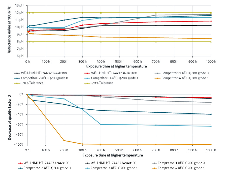
A standard inductance measurement doesn’t always reveal the problem. In a test we performed, ten inductors remained within a plus or minus 20 percent inductance tolerance during 1,000 hours at 200 degrees Celsius. Yet, the Q factor at 2 MHz decreased continuously for some tested parts. Since this factor reflects the balance between inductive behavior and resistance, a falling Q value indicates increasing loss.
Proper selection
Not every application is exposed to the same risk. If the inductor operates with sufficient margin below its temperature and voltage limits, percolation isn’t normally a concern within the expected product life. The risk becomes more relevant where a component operates for long periods close to its limits, especially at high temperature, high switching frequency, high ripple current or with limited cooling.
Start with the true operating profile. Determine the core temperature, not only the ambient temperature or PCB temperature. Define the maximum DC current, ripple current, switching waveform and expected time at maximum load. Rectangular voltage waveforms contain significant high-frequency harmonics, so AC loss data measured under representative conditions is particularly important.
For critical designs, review AC loss and the Q factor at the relevant frequency, then confirm the result in the finished converter. Measure temperature, efficiency and EMI at worst-case load. Repeating these measurements after an endurance test provides a practical indication of whether the design margin is being maintained.
For long-term operation under high thermal stress, consider high-temperature molded power inductors with core materials designed to resist percolation. AEC-Q200 Grade 0 remains valuable, but it doesn’t replace an application-specific assessment of high-frequency loss over time.
Molded power inductors remain an excellent choice for compact, high-current power electronics. However, a proper selection of powder material is essential to their long-term performance. A stable inductance reading alone isn’t proof of stable high-frequency behavior. By assessing the Q factor, AC losses, temperature and lifetime under real operating conditions, designers can select an inductor that supports both converter efficiency and long-term reliability.